Brocade Fabric OS 9.x and Cisco MDS NX-OS 9.x concepts · Fibre Channel with SCSI/FCP · commands identified by system
The fictional host app01 has two independent FC initiator ports. HBA A connects to Fabric A and HBA B connects to Fabric B. Each fabric reaches one FC target LIF on each node of a two-node ONTAP HA pair. The same design can be implemented with supported Brocade switches or supported Cisco MDS switches; the examples are alternative vendor labs, not an instruction to merge unlike switches. All WWPNs, addresses, ports and names in this series are fictional.
About the command and output examples
Names, addresses and results are illustrative. Commands have not been executed against a live storage system or SAN switch for this publication. Confirm syntax and compatibility for your release, then rehearse in an approved lab. Existing-data recovery and destructive changes need an environment-specific plan. Read the editorial standards.
01Understand what the switch transports and identifies
An FC SAN carries storage traffic between an initiator and a target. In these examples the host HBA is the initiator and an ONTAP FC LIF is the target. An FC switch provides fabric services and forwards FC frames; it does not create a LUN or grant that LUN to a host. Management Ethernet is a separate access plane, so a working SSH connection says little about FC data access.
| Term | Meaning | Practical use |
|---|---|---|
| WWPN | Identity of a specific FC port | Use the actual initiator and target LIF identities in zoning |
| WWNN | Node-level FC identity | Do not substitute it for the port WWPN in the ONTAP zoning example |
| FCID | Fabric-assigned 24-bit address | Correlate logins and forwarding; it can change |
| Domain ID | Switch identity within an FC fabric address space | Plan unique IDs inside each connected fabric |
| N_Port / F_Port | Endpoint port / fabric-facing switch port | A normal server HBA logs into an F_Port |
| E_Port | Switch-to-switch fabric link | Joins switches inside one intended fabric |
| NPIV | Multiple virtual N_Port identities on a physical link | Allows virtual initiators or logical storage targets to register |
You can identify the host port, target port, switch port and fabric without confusing their names or addresses.
02Build two independent fabrics before discussing redundancy
Fabric A and Fabric B should have independent failure paths appropriate to the design, including switch connectivity, power and host/storage attachments. An ISL connects switches within one fabric. Connecting the A and B fabrics to each other changes that isolation and is not a shortcut for adding host redundancy. Two VSANs or two logical switches on one chassis can provide logical separation while still sharing that chassis failure.
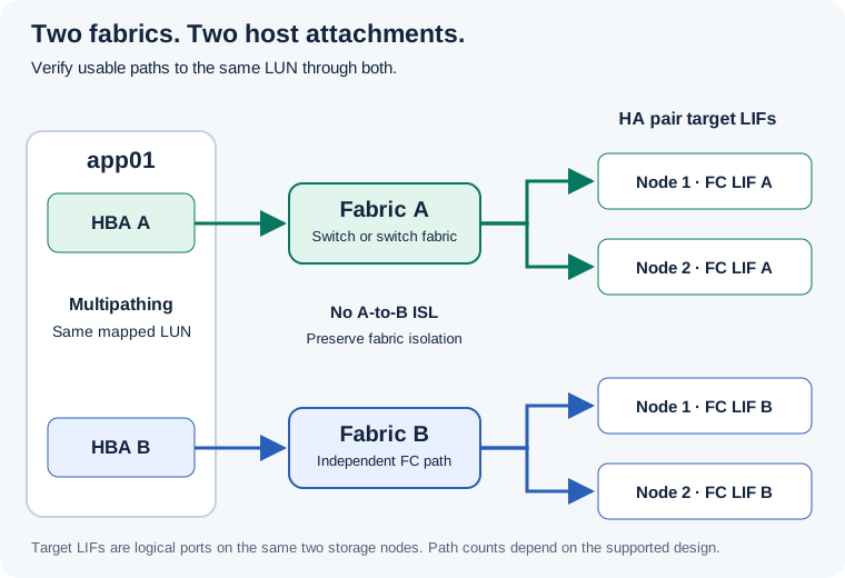
- Draw both host initiators, every switch hop, target LIF and physical controller port. Mark which components share power, adapters, blades or chassis.
- Record supported host multipath settings and the path count expected for a mapped LUN. For this simple two-initiator/two-targets-per-fabric illustration, four paths may be expected; SLM, portsets, platform architecture and host limits can change that number.
- Before maintenance on A, prove current usable access through B from the host and application. Restore and accept A before scheduling work on B.
The diagram and host evidence show two usable service paths with understood shared dependencies.
03Prepare a port and identity worksheet
| Object | Fabric A example | Fabric B example |
|---|---|---|
| Switch / logical context | brocade-a or mds-a; approved FID/VSAN | brocade-b or mds-b; its own approved context |
| Host app01 initiator | 10:00:00:90:fa:aa:00:01 | 10:00:00:90:fa:bb:00:01 |
| Node 1 FC LIF | 20:01:00:a0:98:aa:00:01 | 20:01:00:a0:98:bb:00:01 |
| Node 2 FC LIF | 20:02:00:a0:98:aa:00:01 | 20:02:00:a0:98:bb:00:01 |
| Brocade example ports | Host 0; targets 4 and 5 | Host 0; targets 4 and 5 on the other switch |
| Cisco example ports | Host fc1/1; targets fc1/5 and fc1/6 | Host fc1/1; targets fc1/5 and fc1/6 on the other switch |
| Zoning context | CFG_FAB_A or VSAN 10 / ZS_FAB_A | CFG_FAB_B or independently managed B zone set |
- Replace every value with observed inventory before preparing a change. Verify WWPNs from both endpoint and switch, rather than guessing them from a label or serial number.
- Add rack/U position, serial, model, installed software, license/port entitlement, cable ID, SFP type, peer port, owner and application.
- Keep management addresses out of zoning membership. The switch management IP is not a storage target WWPN. Record actual topology context before any command that changes zoning.
Every intended cable and zone member resolves to a real, owned endpoint in the correct fabric.
04Install the switch and optical connections in order
- Select the hardware installation manual for the exact model and rack kit. Confirm depth, weight, support rails, grounding and service clearance. Director-class installations require their own lifting and module procedures.
- Check airflow direction against the cold/hot aisle plan. Confirm that the installed fans and power supplies match the model’s airflow requirements. Record how redundant power feeds are actually supplied.
- Rack and ground the equipment using the model procedure. Connect management/console access and power, then inspect boot and component health before connecting production fabric links.
- Verify the supported optical transceiver, wavelength, fiber type, connector, speed and maximum reach for each link. Inspect and clean connectors using the site’s optical procedure. Do not look into a live optical port.
- Install the transceiver and fiber in the order required by the hardware guide, route within the bend-radius limits, label both ends, and connect only the approved endpoint. Leave planned production ISLs isolated until fabric compatibility and merge checks are complete.
- Compare the physical worksheet with observed switch ports and endpoint WWPNs. Resolve crossed A/B cables or missing port entitlement before zoning.
Power, cooling, management access, licensed ports, optics and end-to-end cable labels are accepted before the fabric is commissioned.
05Trace login before searching for a LUN
Follow this order when a new host sees no storage: physical link, local login, correct fabric/VSAN/FID, target registration, effective zoning, target-side initiator login, LUN mapping and host multipath/device discovery. This avoids changing a working zoning database to compensate for an unconnected HBA or a missing storage mapping.
| Stage | What it establishes | What it does not establish |
|---|---|---|
| Physical link | A compatible optical/electrical FC connection is online | That the intended WWPN has logged in |
| Fabric login | The endpoint obtains fabric access/addressing | That zoning permits its target |
| Name-server registration | The fabric knows an endpoint’s identity/capabilities | That this initiator is permitted to discover every registered target |
| PLOGI / PRLI | Endpoint and upper-layer protocol session establishment | That a LUN is mapped to this initiator |
| LUN discovery | The storage presents the intended mapped device | That all expected host paths are usable |
| Application transaction | The real service can perform accepted I/O | That a second independent path is healthy |
You can name the last successful stage and collect evidence for the next failing stage.
06Keep zoning, LUN masking and multipathing separate
Zoning limits which FC ports may communicate through the fabric. LUN masking/mapping controls which storage device the target presents to an authorized initiator group. Host multipathing manages multiple paths to the same device. All three need to agree. Broad zoning does not repair an incorrect igroup, and an additional LUN mapping does not make an absent optical link appear.
- Use an approved single-initiator zoning design for the conventional examples. Include the required target LIFs from the appropriate fabric and supported reporting nodes, while respecting host path limits.
- Zone the ONTAP FC LIF WWPNs observed from the storage CLI, rather than the physical adapter’s WWPN. On Cisco, follow NetApp’s restriction that separate LIFs on the same physical port belong in separate zones.
- After fabric access works, verify exact host WWPN membership in the intended igroup and the correct LUN-to-igroup mapping. Compare the host’s persistent device identity before mounting or using a device.
A host has only its intended fabric reachability and LUN access, with supported usable paths.
07Translate the question, not the command name
The Brocade and Cisco procedures intentionally use separate configuration blocks. A Brocade configuration is not a Cisco zone set, and a Cisco device-alias transaction is not a Fabric OS alias. Read-only outputs can also have different scope: local login, fabric directory, logical fabric and effective zoning answer different questions.
| Question | Brocade FOS example | Cisco MDS example |
|---|---|---|
| Which software and switch? | version; switchshow | show version; show inventory |
| Which fabric members? | fabricshow | show topology vsan 10 |
| Did this endpoint log in? | portshow 0; nsshow | show flogi database; show fcns database vsan 10 |
| Which zoning is active? | cfgactvshow | show zoneset active vsan 10 |
| What is saved/defined? | cfgshow | show zoneset vsan 10; show running-config |
| Are errors increasing? | porterrshow; portstatsshow 0 | show interface fc1/1 counters detailed |
| What does the optic report? | sfpshow 0 | show interface fc1/1 transceiver details |
You can choose a read-only command based on the evidence needed and identify the scope of its output.
08Correlate the switch with ONTAP and the host
- Match an observed target LIF WWPN to its switch directory entry and physical uplink. Multiple target WWPNs on one physical uplink can be expected with NPIV.
- Match the host initiator WWPN from its HBA and switch login with the target’s logged-in initiator list. A fabric directory entry is not itself proof of a target session.
- Compare the mapped LUN and host multipath device using persistent identity, capacity and supported path states. Use the OS-specific host procedure for any rescan; do not issue an indiscriminate disruptive bus reset.
# ONTAP admin — read-only examples:
vserver fcp show -vserver svm_lab
vserver fcp interface show -vserver svm_lab
vserver fcp initiator show -vserver svm_lab
lun igroup show -vserver svm_lab
lun mapping show -vserver svm_lab
# Linux host — read-only:
multipath -ll
lsblk -o NAME,SIZE,TYPE,MOUNTPOINTS
# Windows host — read-only:
mpclaim -s -d
Get-DiskThe same endpoint and device identities can be traced across host, fabric and storage.
09Understand credits, congestion and throughput
Teaching calculation: six hosts each requiring 8 Gb/s of sustained traffic to remote targets create 48 Gb/s of aggregate demand before protocol overhead and failure headroom. A single nominal 32 Gb/s ISL cannot provide that total. Adding links can improve aggregate capacity, but it does not mean a single exchange will use every member simultaneously. Measure normal and failure-state demand.
| Observation | Useful next question |
|---|---|
| CRC / invalid-word counters rise | Which receiving link reports it, and what optics/fiber/peer evidence agrees? |
| Credit starvation or transmit wait rises | Which downstream port or endpoint is not draining, and when? |
| An ISL is busy but another is quiet | How are flows distributed, and is the design oversubscribed? |
| Application latency rises without link errors | Do host queues, target load or shared fabric congestion explain the timing? |
A performance conclusion includes interval measurements and a plausible bottleneck, not only the printed port speed.
10Use prechecks and postchecks for every change
| Area | Before | After |
|---|---|---|
| Identity and scope | Switch, FID/VSAN, fabric, release and exact ports | Same intended scope and only approved changes |
| Configuration | Off-switch backup, effective and defined zoning | Expected active membership and retained persistent configuration |
| Hardware | Power, fans, sensors, optics and links | No unexplained new fault or missing link |
| Login and reachability | Endpoint WWPNs and expected sessions | Expected endpoints remain registered and reachable |
| Host service | Device ID, usable path count and transaction baseline | Same device, intended paths and accepted application I/O |
| Recovery | Previous effective policy and scoped reversal plan | Record result, remaining exception and owner |
- Timestamp the evidence and retain both sides of each affected link. Back up the correct logical-fabric/VSAN scope.
- Perform one planned change, review its result, then continue. Do not combine a zone activation, cable move, firmware jump and host driver change into an untraceable experiment.
- If acceptance fails, stop additional changes, preserve outputs and apply the reviewed recovery decision. A full configuration restore or fabric-wide zone disable is not a routine reversal of one new zone.
The change can be reviewed from actual before/after identities, configuration and client service evidence.
11Follow the lab in a basic-to-advanced order
- Start with the hardware and identity worksheet and inspect a healthy fabric without making changes. Explain every port and login in the worksheet.
- Follow the vendor’s basics guide to prepare an isolated host-facing port and verify local registration.
- Use the vendor’s zoning guide to add one approved host-to-target zone, activate through the correct mode, and validate the mapped test LUN.
- Read the advanced guide before adding an ISL, logical fabric, NPV/Access Gateway topology or firmware upgrade. Each has different scope and failure behavior.
- Use the troubleshooting guide to explain a missing login, wrong zone, CRC delta and lost path. Rehearse failures only in the approved lab.
- Answer the interview scenarios by giving evidence, a decision and an acceptance test. Keep your observed results separate from this site’s fictional examples.
You can complete and explain a host connection, diagnose a failed stage and prove service after a scoped change.
Use the section links to revisit a step, or follow a related guide below.
Official references and further reading
Choose the matching release in the vendor documentation before using a command or design. References open on the publisher’s website; linked material remains with its publisher.
- NetApp: FC zoning concepts and LIF WWPNs
- NetApp: zoning designs, multipathing and Cisco restrictions
- ONTAP: FC target LIF inventory
- ONTAP: logged-in initiators
- ONTAP: LUN mappings
- Cisco: MDS 9148T model-specific hardware installation
- Cisco: MDS 9148T optical and management connections
- Cisco: VSAN configuration